This page will highlight some of the projects I've worked on. The top section is a list that will link to more complete sections below.
These projects are currently sorted chronologically.
Projects List (links to details)
Distributed Light Controller Prototyping April 2019-July 2019
-
Project Overview
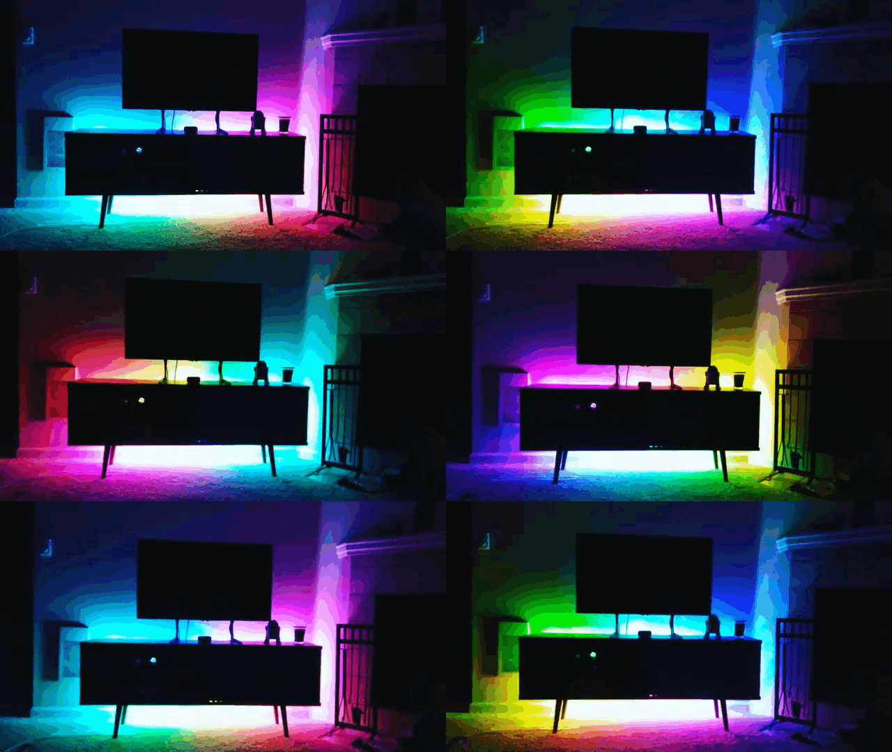
Following from my fascination with WS2812 addressable LEDs, I wanted to add controllable lights to my home. I set out to create a proof of concept project that would enable me to control light strings from a web browser, allowing anyone in my home to change the lights.
-
Hardware Overview
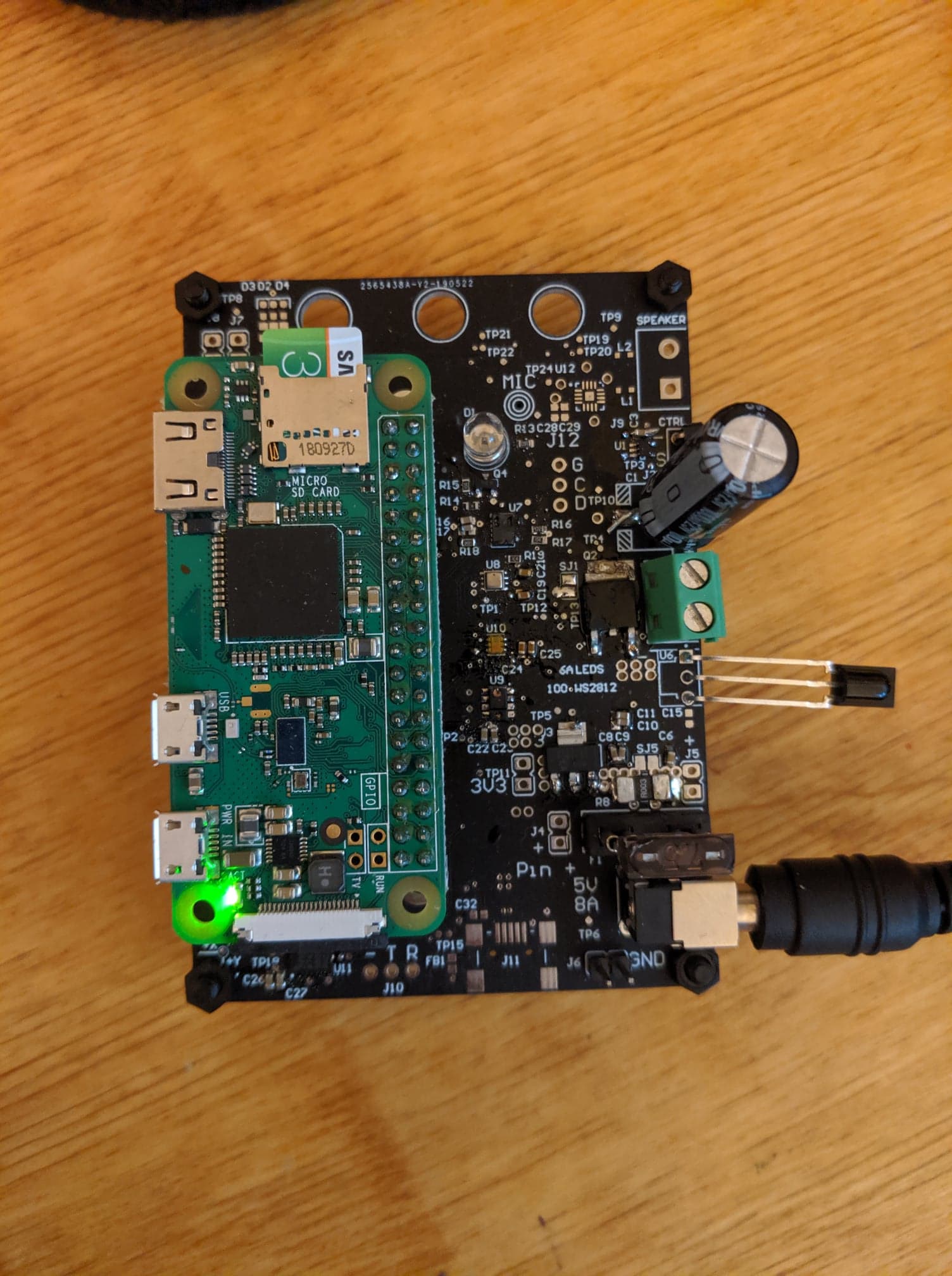
The light controller is a daughterboard for a Raspberry Pi Zero W. Power to the lights is controlled through a transistor. Additional sensors on the daughterboard are available to monitor the environment.
-
Software Overview
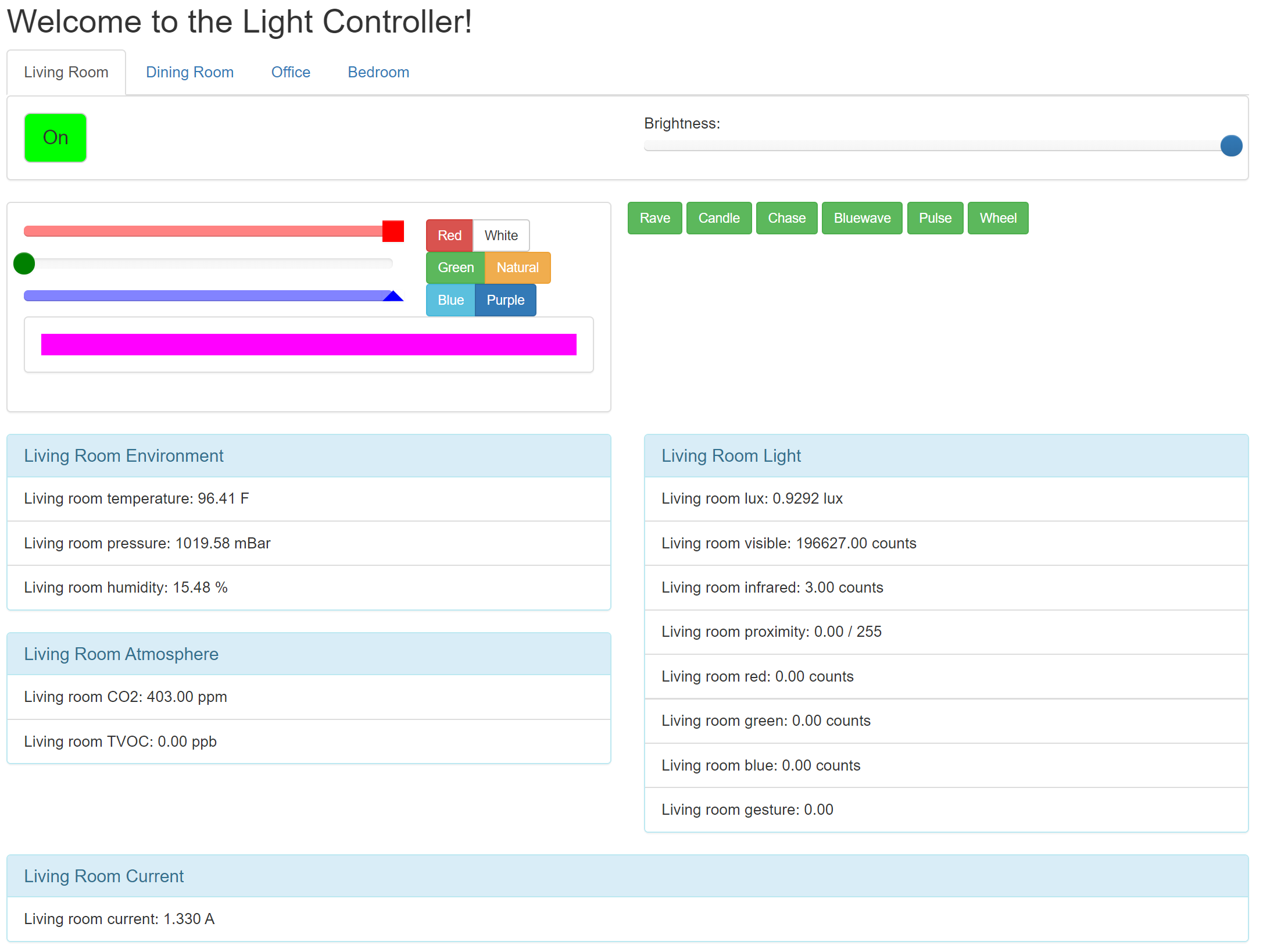
The website is a Flask web server. Button clicks cause Javascript callbacks to update the server with new commands. The server application will publish command updates to an MQTT broker, hosted on the same computer as the server. The MQTT broker then routes the command to the appropriate device.
-
Files
-
Pictures
FPGA Digital Audio Mixer January 2019-March 2019
-
Project Overview
I have an old computer at my desk I use to watch videos while I'm working on projects. Sometimes I would like to hear sound from both devices, so I resolved to build an audio mixer. Wanting to review some FPGA fundamentals, I decided to implement this with digital logic.
-
Hardware Overview
The core of the project is a Microsemi SmartFusion2 SoC, a Cortex-M3 microcontroller connected to FPGA fabric. The SmartFusion2 is connected to 3 I2S ADCs sampling from 3.5mm audio jacks (like connecting to the aux port in a car), and one I2S DAC and amplifier to power headphone output. Additionally, it's connected to four rotary encoders that could be used to control volume, and a set of dip switches that can be used for configuration. Additionally, an ESP8266 is connected with SPI for a future upgrade path to pass audio over the internet.
-
Software Overview
The Cortex-M3 processor in the SmartFusion2 performs initialization tasks. This initialization script is written in C, built with the Microsemi supplied hardware abstraction code. The Microsemi tool SoftConsole was used to develop, build, and deploy the software. The I2S DAC needs registers set over I2C to put it in the correct mode, including configuring it to act as an I2S master, setting the clock speed, setting the volume, and setting the clock speed.
-
Firmware Overview
The firmware is written in Verilog and built and deployed with the Microsemi tool Libero. The firmware generates a master clock to send to the I2S ADCs and DAC, and reads the bit clock and word clock generated by the DAC. This bit clock and word clock is passed through the FPGA to the ADCs. As the ADCs generate data, the firmware reads the values, merges them with the other channels, and passes te result back to the I2S DAC.
-
Files
-
Pictures
-
Failures and Lessons Learned
This project was an exercise in re-learning the basics of FPGA design, and reviewing practical "high-speed" (40MHz) signal layout concerns. It took a lot of testing and re-design to create a more complete understanding of the correct way to pass signals through multiple clock domains in Verilog.
High Altitude Balloon ControllerJanuary 2018-April 2018
-
Project Overview
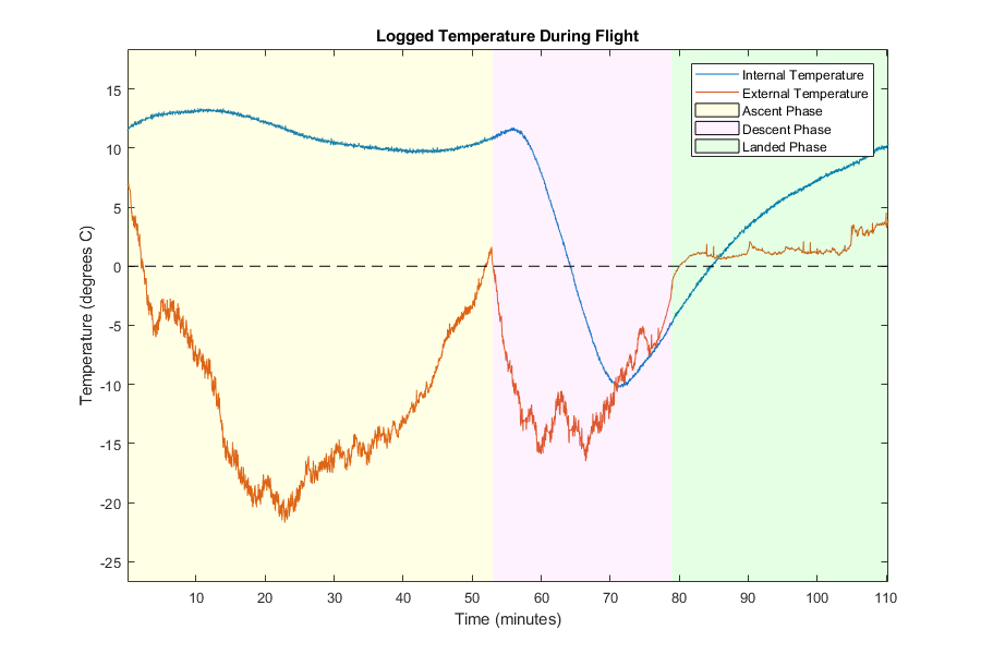
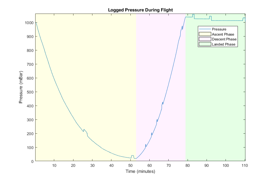
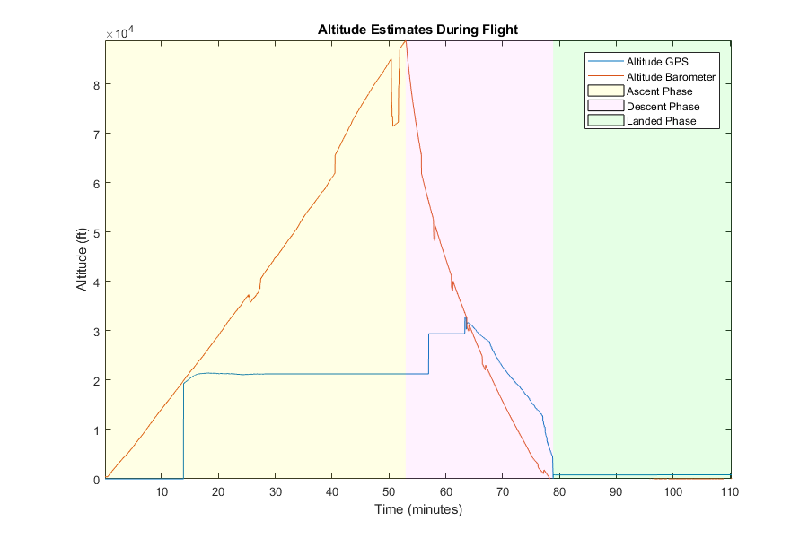
The final project for SPACE 584, Space Instrumentation, was to launch a high altitude balloon and collect telemetry data. To collect telemetry, we needed to use a microcontroller and design a printed circuit board for interfacing. We had to perform thermal, shock, and endurance testing on the telemetry device and housing.
-
Hardware Overview
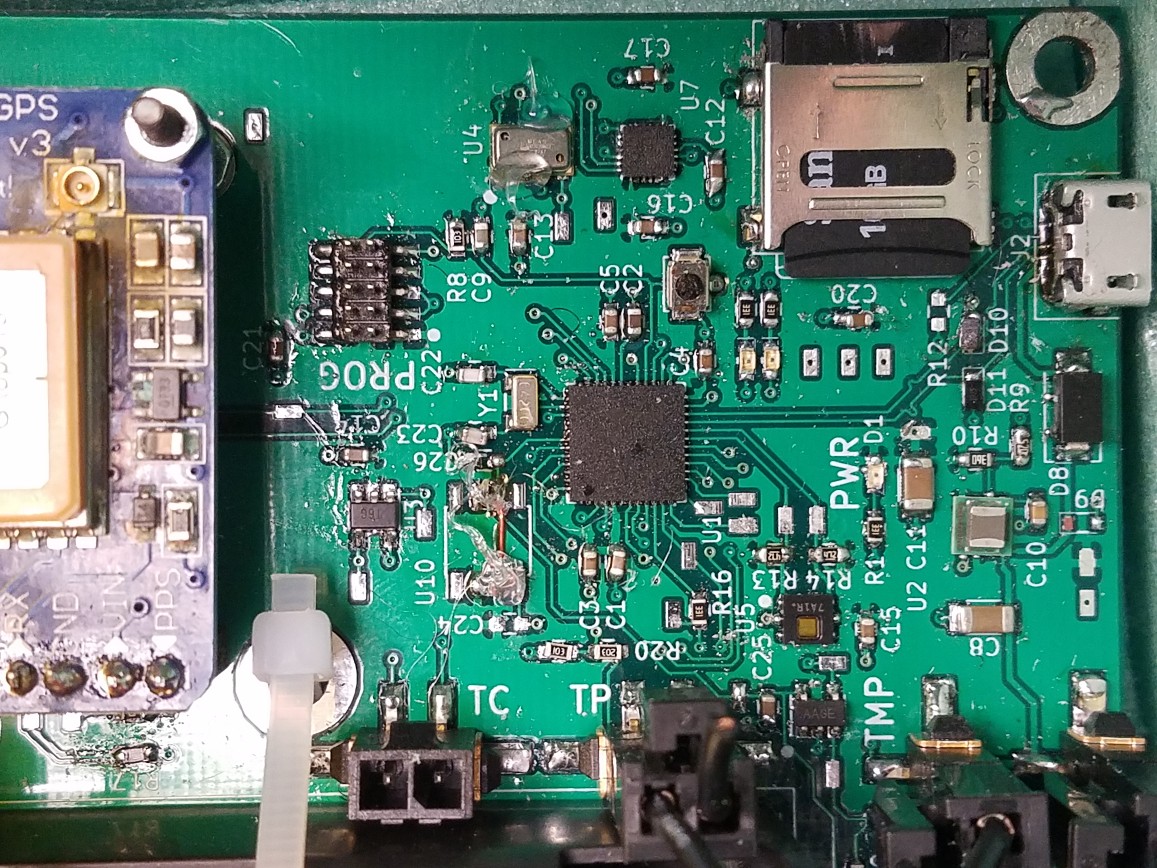
We used an Atmel SAMD21 microcontroller as the sensor sampling and data logging controller. It was connected to a barometer over SPI, a humidity sensor over I2C, a 9-degree of freedom inertial measurement unit over SPI, a GPS module over UART, a battery level sensor through analog input, a board temperature sensor through analog input, and an external thermistor through analog input. It also had two drive circuits for powering two 5W heaters. Power was provided to the microcontroller and sensors by stepping down the battery through a buck converter. The microcontroller was also connected to a SD card for data logging. A footprint for a radio was added for a future live telemetry option, but the radio ended up not having enough power to transmit over our desired range (the datasheet said it was 1W, it ended up being closer to 250mW).
-
Software Overview
The software implementation was written in the Arduino infrasturcture to speed up the development process. Initial prototyping used FreeRTOS to schedule sensor sampling and data logging tasks. The flown code ran in a super-loop architecture, where each sampling task was serviced at a specified interval. A sample for a time instance was placed in a struct and then pushed to the SD card with a time slice in a binary format with a checksum. Once the data was logged, we had a set of Python scripts to convert the logged binary data to a CSV file, that was then processed and plotted with MATLAB.
-
My Contributions
I collaborated on the architecture design and schematic design, did the board assembly and hardware debugging, wrote the microcontroller code, and wrote the data post-processing scripts.
-
Files
-
Pictures
-
Failures and Lessons Learned
During the design of the printed circuit board, we made a few minor mistakes. The first was a mis-reading of the analog power bus datasheet. We assumed we could power the analog subsystem with one voltage and then provide a separate external precision reference, as we were doing with similar projects using an STM32 microcontroller. However, once we realized the microcontroller wouldn't boot, we found a note in the datasheet stating the system voltage and the reference voltage needed to be the same. A minor wire jump and a trace cut fixed the problem. We also made a footprint mistake on the barometer wiring (we configured it for I2C but connected it to the microcontroller for SPI), which required a much more involved modification to fix (and a lot of epoxy to hold it down for flight). In the thermistor circuit, we had an issue where the harness connecting to the microcontroller was the perfect length to act as an antenna for the 144MHz tracker radio. We mitigated the noise injection by twisting the wires in the harness and removing the artifacts in software.
Digital Segway ControllerMarch 2018-April 2018
-
Project Overview
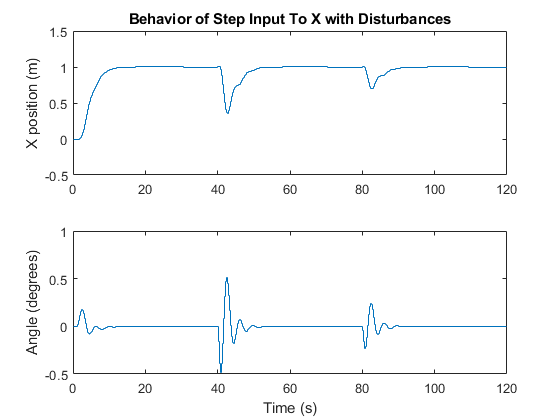
As a final project for EECS 561, Digital Control Design, we were asked to choose a real world system and create a digital controller around it. My team chose a Segway, as it seemed like a complex and interesting system. The model included Segway dynamics and motor dynamics. To keep the scope of the problem bounded, we chose to only model and control the Segway in one dimension. We created an architecture for the angle of the Segway (how far the handle bar is from vertical) and for the change in lateral position of the Segway. Our final project report is attached at the bottom of this section.
-
Control Overview
We architected two controllers for this project. The first was an inner loop/outer loop controller, where Segway angle was the inner loop and lateral position was the outer loop. The second was a full-state feedback LQR controller with an integrator augment and estimator for disturbance rejection. Process noise, measurement noise, and step disturbances were added to this model to test robustness. Full-state feedback was required for this model to accommodate significant deficiencies in the model we found, and the estimator was designed with pole placement for the same reason.
-
My Contributions
I lead the architecture design for both controllers, and then implemented and tuned the full state feedback controller.
-
Files
-
Pictures
-
Failures and Lessons Learned
Many of the issues we faced during the course of this project were due to issues with the model. Trusting that it was correct because it was in a published paper was a mistake on our part.
Head Sensor SuiteSeptember 2017-December 2017
-
Project Overview
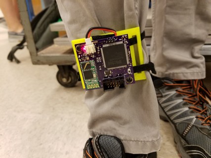
The final project of EECS 473: Advanced Embedded Systems, required the creation of a device that could serve a meaningful purpose that used a microcontroller. My team decided to create a head-worn device that could provide alternative control input into a computer instead of using a mouse. We wanted to test a variety of sensor inputs; head/eye tracking, sound control, inertial control, and electromyography event control.
-
Hardware Overview
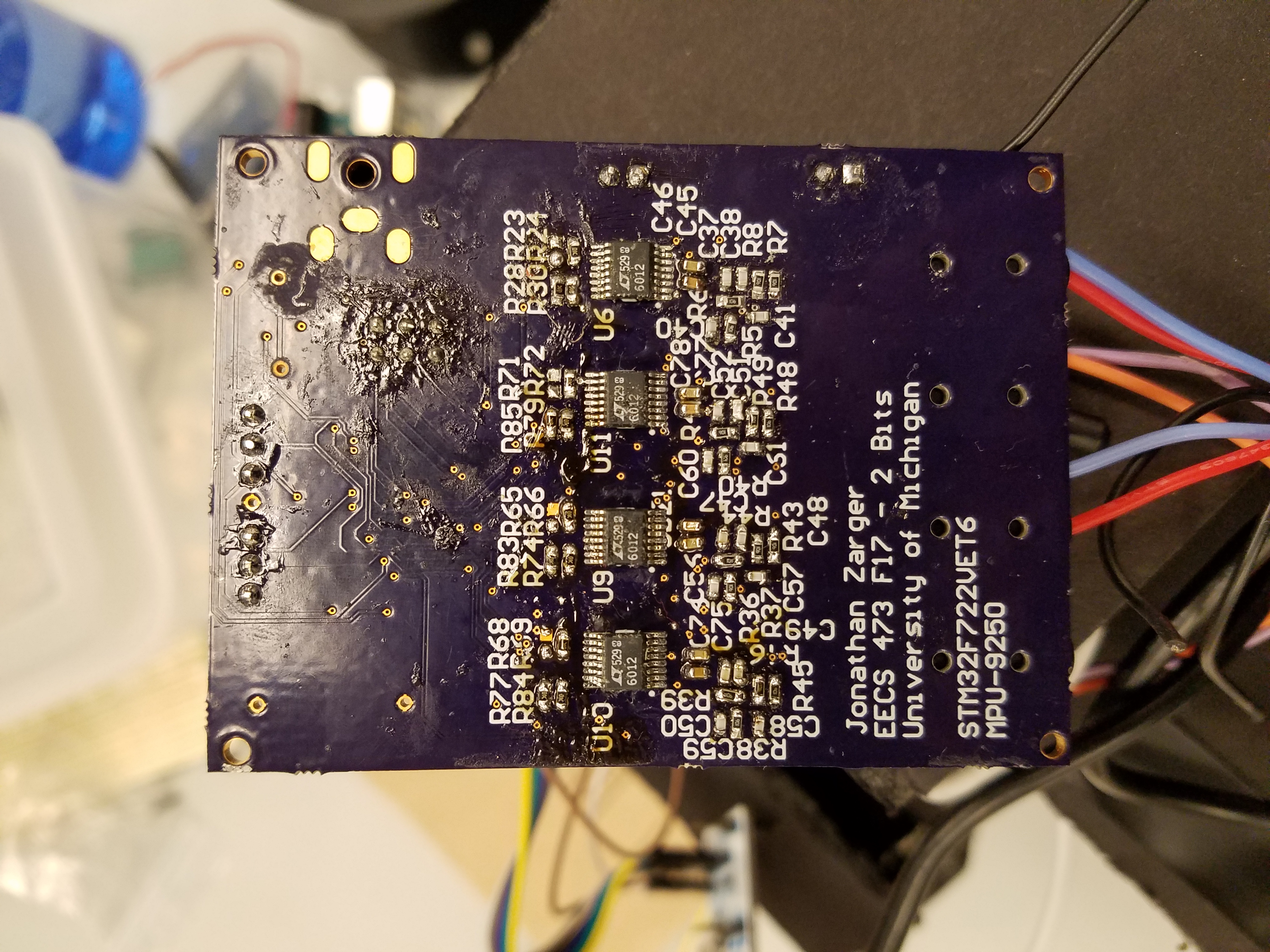
The project was the combination of several pieces of hardware. The primary control computer was a Raspberry Pi single board computer running Linux. This board interfaced with the video and microphone systems. The Raspberry Pi interfaced with a custom printed circuit board data acquisition and processing board that had analog circuitry for the electromyograpy electrodes and a connection to the SPI controlled inertial measurement unit. THe sampling and data control was performed with an STM32M7 family microcontroller. The schematic in the Files section describes this printed circuit board.
-
Software Overview
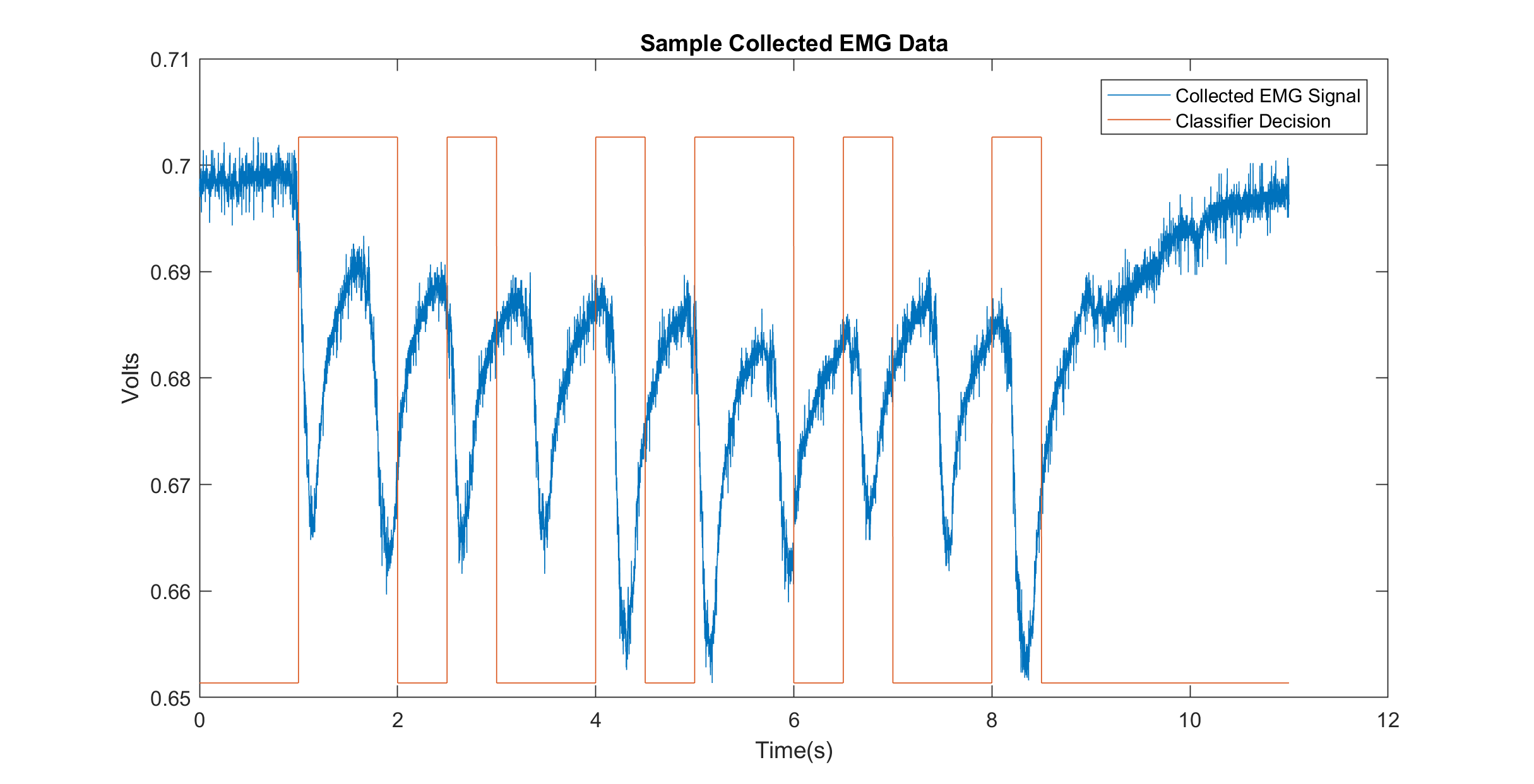
My focus on the project was the electromyography and the inertial sensing. For the electromyography signals, a logistic regression based classifier was trained on the desired events and the trained results were used to capture muscle motion events in read time to trigger mouse motion. The inertial sensing used a simple threshold around a deadzone on the X and Y acceleration axes to determine how much mouse motion should occur.
-
My Contributions
I did the design, prototyping and test of the electromyography circuit. I did the part selection, schematic capture, prototyping, board layout, assembly, debugging and verification of the printed circuit board. I did the initial microcontroller testing. I developed, analyzed, and tested the logistic regression based classifier (as well as an unusable subspace learning classifier) for the electromyography event detection.
-
Files
-
Pictures
-
Failures and Lessons Learned
I made a bad assumption about part availability, and ended up having to choose a different microcontroller model at the very last minute. This change necessitated re-doing a significant chunk of the schematic and board layout.
We also discovered significant issues working with the electromyography probes. I didn't build in an adequate front end for common mode dissipation, and we had issues with the probes making poor (or no) contact with the face. We eventually mitigated these with software and with careful practice attaching the electrodes.
Lidar Point Cloud VisualizationNovember 2017-December 2017
-
Project Overview
In MECHENG 599: Self-Driving Cars, the final project involved using deep learning to count the number of cars in sets of camera images generated from the course staff from a video game. An optional section stage of the project involved image segmentation of the cars with an estimate of their distance. A LIDAR point could was provided with the same timestamp as a camera image to provide supplemental information. Our teams proposed solution involved projecting the LIDAR point cloud into the camera frame and generating a filled depth map in the same resolution of the camera to train on.
-
Software Overview
A 3D LIDAR point cloud and a camera projection matrix were provided. My script took each point cloud and used the projection matrix to align a representation of the point cloud with a corresponding camera image. The distance from camera was used to create a visual representation of depth in grayscale to compare against the camera image. A nearest-neighbor interpolation was applied to groups of pixels to estimate how the spaces between the LIDAR point measurements should be filled in. Different size blocks were selected as a tradeoff between processing time and accuracy of representation.
-
Pictures
Motion Based Game ControllerFebruary 2017-April 2017
-
Project Overview
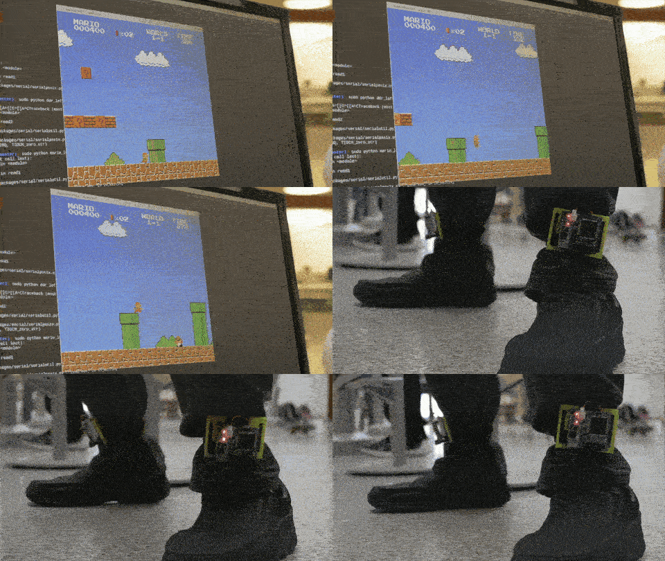
This was the final project for my EECS 373: Microprocessor Based System Design class. My team and I chose to design and build a device to measure user motion data and transfer it wirelessly to a laptop. This input could be used for various things, and was designed with the intent of using it as a simple game controller.
-
Team Members
Brandon Waggoner: application software, motion software design, and algorithm prototyping
Jacob Sigler: schematic design, printed circuit board layout, electrical assembly, and mechanical assembly
Me: schematic design, electrical debugging, Verilog implementation, microcontroller C development
-
Project Motivation
Brandon is a serious fan of the game Dance Dance Revolution, and thought it would be cool to try to build a way to play it anywhere without needing a large, bulky mat. The true (though ultimately unmet) goal of this project was to create that device.
With that in mind, the hope was to design the device so that we would be able to detect forward/backward and left/right foot motion, as well as hit detection motion (a foot hitting the ground and lifting off). With these basic features, we would be able to use the resulting project to play Dance Dance Revolution without a mat.
-
Electronics Architecture
The architecture diagram in Files and in Pictures below shows how parts are connected.
The primary device in this project was the Microsemi Smartfusion microcontroller/FPGA SoC. We used a chipset in the same family for in-class labs, and were therefore encouraged to use this device as the main processor for our project. The microcontroller has an ARM Cortex-M3 processor, connected to FPGA fabric through an APB bus.
The Smartfusion SoC is connected to an Invensense MPU-9250 inertial measurement unit to record motion. It is a 9-degree of freedom sensor. It communicates with this device through a SPI bus.
The device was powered by a single-cell lithium ion battery. Low dropout linear regulators were used to power the systems on the device from the battery. The microcontroller monitored the current battery state using a battery monitoring chip through I2C.
The device communicated wirelessly to a remote laptop through Bluetooth. The hobby-user standard HC-05 Bluetooth module was chosen for this project. It communicates with the Smartfusion SoC through UART.
-
Software Architecture
The microcontroller interfaced with the sensors and did the motion state estimation with C software. The microcontroller used a Mahony Filter to fuse magnetometer, gyroscope, and accelerometer data together to create an inertial frame. We applied a direction cosine matrix to this frame so the microcontroller could process motion in a world frame. We attempted to characterize this motion through data collection and analysis, but we ran out of time to create an effective complete motion estimation algorithm.
It also communicated with the FPGA through an APB bus. The FPGA controlled timers that the microcontroller read from through the APB bus. We had experimented with doing some of the signal processing and state estimation on the FPGA, but ran out of time.
-
My Contributions
I worked on the hardware architecture, creating the electrical schematic, creating the bill of materials, setting up the software development environment, assembling the printed circuit boards, debugging the printed circuit board, writing the C for the microcontroller, and writing the Verilog for the FPGA.
-
Files
-
Pictures
-
Failures and Lessons Learned
With the time constraints for the project, we only ended up having a hit detection controller. We hadn't anticipated issues with coupling caused by translating acceleration data between frames, and needed more time to refine our motion algorithm. Our board mount also fit too loosely onto a leg, and needed to be redesigned to avoid sloppiness in the acceleration data caused by the looseness.
Hands on Robotics ProjectsJanuary 2017-April 2017
-
Project Overview
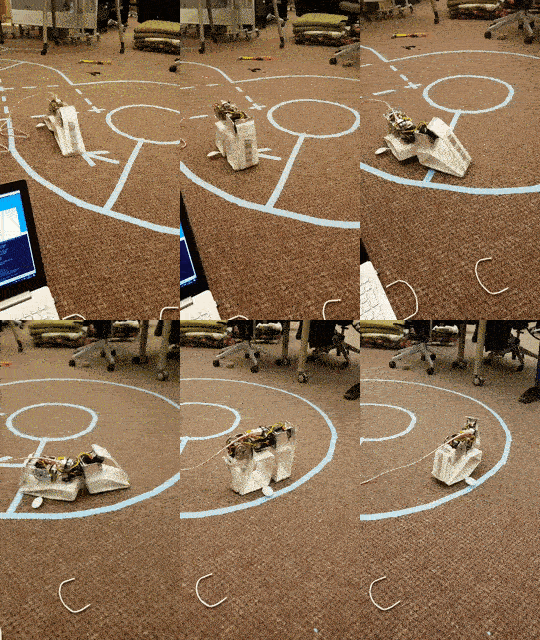
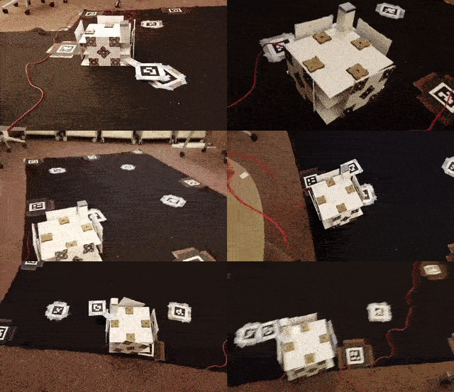
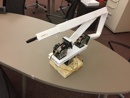
EECS 498: Hands on Robotics had 3 projects over the semester. Teams of 3 or 4 completed these projects.
The first project was to build a robot that could travel without fully rotating parts. The second was to build a robot that could autonomously traverse through a set of points. The third was to build an arm that could draw on an arbitrarily placed (with constraints) piece of paper.
-
Team Members
The teams were different for each project.
-
Project Motivation
The first project was an introduction to building robots using foamcoare and tape, to posable programming, and to using the provided software libraries to control what we built.
The second project was an introduction to controlling a robot with very limited sensor data, handling error in a dead-reckoning scenario, and trying to build a robot that behaves consistently enough to model the error.
The first project was an introduction to inverse and forward kinematics, working with rotating frames, and building robots that compensate for gravity.
-
Software Architecture
In this class, we used Python to control the robots. The actuators were connected to a laptop running this Python software through a tether. The professor running the class provided us with Python libraries to communicate with the actuators, as well as some base code for generating tasks to run in parallel, and for developing with posable programming.
-
My Contributions
For the first two projects, I wrote all of the software required. For the third project, I helped design a simulation of the forward and reverse kinematics of our robot, and then helped write the control software.
-
Files
Project reports not posted, these projects may be used again so it should not be posted online as it contains guidelines and instructions on how to complete the project. -
Pictures
DOGBOT: Laser Following RobotOctober 2016-December 2016
-
Project Overview
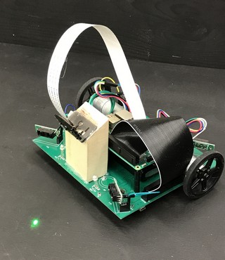
This was my senior capstone project for EECS 452: Digital Signal Processing Lab. The goal of this project was to create an interesting demonstration using DSP. We chose to design a robot that would be able to chase after a laser pointer.
-
Team Members
Andrew Levin: Image Processing Design, Optimization, and Tuning
Shiva Mehta: Image Processing Design, Optimization, and Tuning
Me: Electrical Design, Microprocessor Software, Embedded Linux Application Architecture
-
Project Motivation
Inspired by the way a dog or a cat would chase after a laser pointer, we wanted our project to be fun to watch and interact with. We designed it to have fast and reliable laser detection algorithms with image processing, and designed our own chassis out of a printed circuit board so that we could have motors that would be able to follow the laser as fast as we could detect it.
-
Electronics Architecture
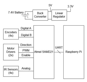
The architecture diagram in Pictures below shows how parts are connected.
The primary device in this project was a Raspberry Pi 3 single board computer. It was connected to a camera to search for the laser, and connected to a microprocessor through UART.
The Raspberry PI connected to an Atmel SAMD21 microcontroller. This microcontroller drove the motors at the desired speed, determined wheel speed from the encoders, and used infrared distance sensors to avoid colliding with the walls.
The microcontroller interacted with two H-Bridge ICs, which were connected to the motors. The ICs had integrated transistors and gate drive circuitry, as well as debugging and fault detection over SPI.
The microcontroller was connected to four analog infrared measurement sensors, one on each corner of the robot chassis. They output a voltage proportional to their distance to a wall, and had a range that allowed to robot to have an accurate estimate of it's location relative to the walls around it.
All systems were powered by a 2 cell lithium polymer battery. The Raspberry Pi was powered by a 5V switching regulator off of the battery, and the other subsystems were powered by a 3.3V linear regulator.
-
Software Architecture
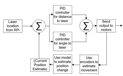
The software for the microprocessor was based on the Arduino platform, which is derived from C++. The microcontroller had interrupts set up to trigger for the encoders. When those weren't triggering, the robot used it's internal state model to estimate where it was relative to the last known location of the laser. It listened over UART for messages from the Raspberry Pi image processing software for new laser location estimations. A closed-loop controller was used to zero the error in the difference between the current location estimate and the location of the laser.
The Raspberry Pi ran Python software to perform the image processing. The software ran on four different process threads. The first collected images from the camera. The second and third threads used OpenCV to determine where the laser was relative to the robot. The fourth thread transmitted the laser location to the microprocessor over UART.
-
My Contributions
I created the electrical schematic, did the mechanical layout for the printed circuit board, assembled and debugged the printed circuit board, created the bill of materials, wrote all of the microcontroller Arduino C, wrote the control algorithm, wrote the observer algorithm, tuned both of those sets of algorithms, created the image processing software architecture for the Raspberry Pi, helped prototype with OpenCV, and modified our laser pointer to extend the battery life by orders of magnitude.
-
Files
-
Pictures
-
Videos
-
Failures and Lessons Learned
Sometimes the fine print is missing from the documentation! The documentation for the motor encoders didn't specify whether the encoder count/rotation value was before or after the gearing. I assumed it was accounted for, it was not, and my microcontroller's quadrature decoding in software was too slow to handle full quadrature decoding. I only had enough CPU power to determine wheel velocity. I had to assume direction from an assumption based on which way the motors were powered.
Non-linearities (mainly saturations) in the way I designed the laser-following embedded controller caused significant issues in handling. The coupling between my two controllers was caused by my incorrect initial assumption that there would be non-negligible interaction between distance estimation and angle estimation. The saturations on both controllers generally caused one to be more dominant than the other, causing the robot to turn and not move towards the laser, or move towards the laser but not turn.
MASA Hybrid Control + Telemetry DeviceAugust 2015-April 2016
-
Project Overview
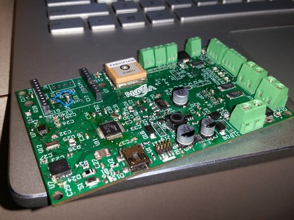
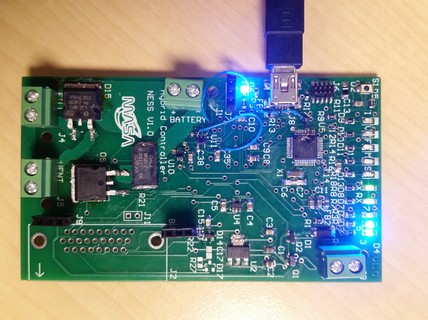
The goal of this project was to design flight hardware and software to control a 2015/2016 version of the Michigan Aeronautical Science Association's (MASA) development hybrid engine. The project scope increased so that it could function as a locator beacon, or as a parachute deployment.
For this version of the engine, the controller needed to be able to open and close two solenoid values and a servo attached to a ball valve to fill the oxidizer tank and release oxidizer for ignition from inside the rocket. It had a GPS and a wireless transmitter to act as a beacon, and an accelerometer and barometer to act as a parachute deployment controller.
-
Project Motivation
The initial version of control for this project was a temporary solution built on a perfboard that would not be able to survive a flight. The hope of this project was to design a system that would be able to be used in flight.
-
Electronics Architecture
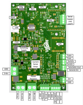
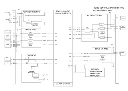
The architecture diagram in Pictures below shows how parts are connected.
The primary device in this project was an Atmel SAMD21 microcontroller. It interfaced with all of the sensors, and the servo and solenoid control.
Three large transistors were used to drive the solenoids and to enable or disable the servo. A gate drive IC was used to allow the microcontroller to enable the transistors. The power path for the transistors ran through power resistors, which were connected to amplifiers used to estimate the current
The microcontroller is connected to two motion measurement sensors and a barometer. One is a 9 degree of freedom inertial measurement unit over I2C, one is a two degree of freedom accelerometer over SPI. THe barometer is also connected over SPI.
A GPS module was also added to this project. It has a built-in ceramic antenna, and communicates with the microcontroller over UART. A slot was added onto the board for an XBee wireless radio module. MASA owns several 100mW 900MHz modules that can be used to get telemetry from a serval mile distance. The microcontroller communicates with this module over UART as well.
The system was designed to be powered from a number of different sources. A 3 cell or 4 cell lithium polymer battery (for powering the solenoids), a 2 cell lithium polymer battery (for powering the servo), or through USB for debugging.
-
Software Architecture
The software for the microprocessor was based on the Arduino platform, which is derived from C++.
-
My Contributions
I created the electrical schematic, did the mechanical layout for the printed circuit board, assembled and debugged the printed circuit board, created the bill of materials, wrote sample software to pass to teammates, and supervised software development by teammates.
-
Files
-
Pictures
-
Failures and Lessons Learned
This was at the beginning the most significant embedded systems project I had ever undertaken, so I learned many little things along the way, like being meticulous in my bills of materials (after ordering a number of important wrong parts), being thoughtful with layouts (after having to redo significant portions, not making things more complicated than they need to be (this board has way too many power selection options), and getting requirements in writing (as they changed constantly around me without).
MHacks HackerboardsNovember 2015-October 2016
-
Project Overview
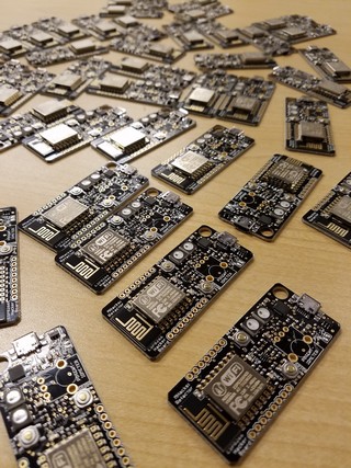
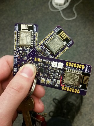
The goal of this project was to design and build a development tool to pass out at MHacks Hackathon events. It was passed out at MHacks 7 in February 2016, MHacks 8 in October 2016, and MHacks 9 in March 2017. I was involved in MHacks 7 and 8. The website for this project lives at this site.
-
Project Motivation
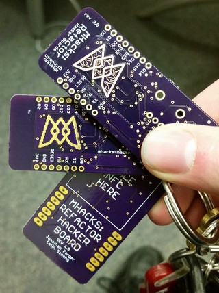
The MHacks hardware team wanted a piece of hardware that could be used to supplement an introduction to hardware workshop. We wanted to build a tool that we could use to teach the basics to an audience of primarily people who have never used hardware, though have significant software experience.
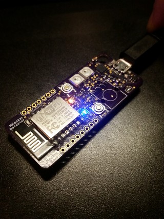
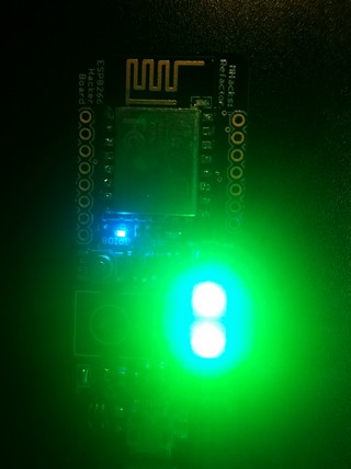
The Hackerboard platform was designed around the popular ESP8266 because of it's thorough support for development through Arduino. We added LEDs to use as a basic demonstration, addressable LEDs to use as an advanced demonstration, and a spot for a large potentiometer to teach basic soldering.
-
Team Members
Colin Szechy: Schematic design, PCB layout, software design, website, workshop design
Me: Schematic design, PCB layout, software design, website, workshop design
-
Electronics Architecture
The main component of these boards is an ESP8266 module. It is well known as an Arduino compatible microprocessor system with a built in WiFi radio.
The ESP8266 was programmed through a CP2104 USB to Serial bridge. This can also be used as a debugging interface.
The ESP8266 communicated with two WS2812B LEDs. They are addressable LEDs, which means they are chained together and have programmable RGB levels.
The power electronics for this project were very simple. A linear regulator took 5V from a USB port and converted it to 3.3V for the rest of the system.
-
Software Architecture
The software for the microprocessor was based on the Arduino platform, which is mostly C with some C++. We wrote some examples projects on the project website.
-
My Contributions
I worked on the schematic, the layout, and the example software. I also helped design and run the Introduction to Arduino and Hardware Workshop.
-
Files
-
Pictures
-
Failures and Lessons Learned
For MHacks 7, Colin and I decided to get together a team and assemble 100 boards by hand to pass out at the event for cost saving. Our quality was not nearly as high as a professional fabrication house, and our yield rate was <75%. We did not try to hand assemble that quantity of boards at the next event, and instead got them professionally assembled.
Quadcopter Outer Loop GNCApril 2016
-
Project Overview
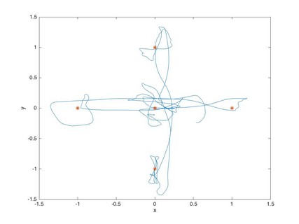
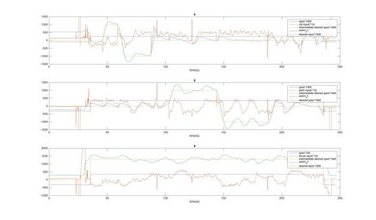
The goal of this AEROSP 450: Flight Software Systems final project was to autonomously fly a quadcopter through a set of coordinates in space. This involved designing an outer loop controller, a guidance algorithm, and a navigation algorithm. This was done on a Beaglebone Black running Debian Linux with C. The quadcopter flew within a set of cameras that defined an absolute coordinate system with feedback, allowing the system to always have a good estimate of location.
-
Project Motivation
As the final project for a flight software systems class, this project needed to show a grasp on a set of relevant flight software skills. These included real-time software development, control system design, guidance/navigation design, debugging, and testing.
-
Software Architecture
This project was written in C on an embedded Linux platform. There were several different threads in the program that handled different tasks. One thread communicated with Optitrack, a camera system that defined an absolute coordinate system for the quadcopter. One thread interfaced with the wireless transmitter, which sent updated commands to the quadcopter's motor controllers. Another thread handled the state model of the quadcopter, and used it to determine how the motor control inputs should change depending on the desired location to move to.
-
My Contributions
I designed the GNC algorithms, implemented them in C, tested them in-flight, and tuned them as needed.
-
Files
Final report not posted, this project may be used again so it should not be posted online as it contains guidelines and instructions on how to complete the project. -
Pictures
-
Videos
This is a video of my successful flight at the end of the semester!
Magnetic Levitation Feedback ControllerMarch 2016-April 2016
-
Project Overview
The goal of this EECS 460: Control System Analysis and Design class final project was to design, simulate, and test a feedback controller for a magnetic levitation system. The task was to create a stable control system to cause a ball to levitate in a magnetic field. Given a system model, a position sensor for ball to levitate, and a current control system for the coil, I designed and tuned a successful control system.
-
Project Motivation
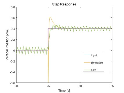
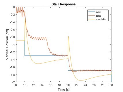
The magnetic levitation problem presented in this project is just an example of the classic inverted pendulum problem. It is a second-order non-linear system, and we try to force the system to an unstable equilibrium. A linearized model was used for controller design, it was simulated against a non-linear control model with MATLAB and Simulink, and then it was tested on real hardware.
-
Control Architecture
Our final controller was a PID controller, tuned against the linear model. One constant was fixed, another iterated against, and one tuned with root locus analysis. A precompensator was added to fix issues with overshoot.
-
My Contributions
This was a team project. Each team member designed a controller, and we compared simulation results. Mine was chosen for optimization and use on hardware.
-
Files
Final report not posted, this project may be used again so it should not be posted online as it contains guidelines and instructions on how to complete the project. -
Pictures
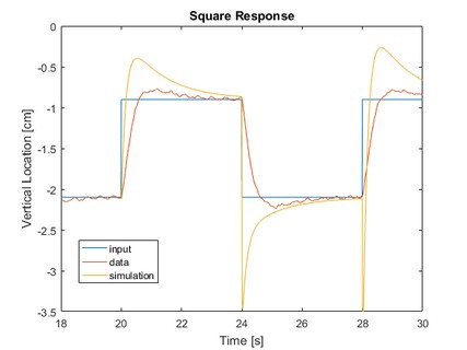
The artifacts at the discontinuities of the simulations were ignored for the purposes of design/tuning. -
Failures and Lessons Learned
"All models are wrong, but some are useful". A lot of this final project was finding the ways that running a controller against the non-linear model made it unstable, and attempting to compensate for the issue.
Tablesat Satellite SimulatorMarch 2016
-
Project Overview
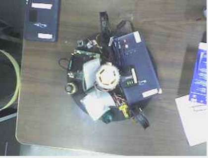
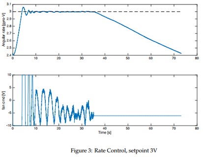
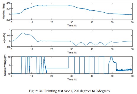
The goal of this AEROSP 450: Flight Software Systems midterm team project was to design, implement, and test software to control a physical (very simplified) satellite simulator system called Tablesat. Tablesat has two computer fans that can be powered to make it rotate, a gyroscope to measure angular velocity, four light magnitude sensors, and a three axis magnetometer. The end goal of the project was to design a constant rate controller, and an absolute position controller.
-
Project Motivation
The important aspects of this project were implementing control algorithms, and state estimation algorithms on limited resources. QNX was to develop and run software on. This allowed us to develop better real-time software.
-
Software Architecture
This project was written in C on an embedded Linux platform. There were several different threads in the program that handled different tasks. One thread polled the analog-to-digital converted on the microcontroller to get updated magnetometer and gyroscope measurements. Another thread handled the state model of Tablesat, and used it to determine how the motor control inputs should change based on the desired speed or position. This thread also performed significant low pass filtering on the measurements, especially on the magnetometer to compensate for the added noise from the motors.
-
My Contributions
I wrote most of the implementation software, and did the debugging and tuning of the controls.
-
Files
Final report not posted, this project may be used again so it should not be posted online as it contains guidelines and instructions on how to complete the project. -
Pictures
Adaptive Cruise Control and Lane Keep Embedded SoftwareNovember 2015-December 2015
-
Project Overview
The goal of this EECS 461: Embedded Control Systems team project was to design, implement, and test software to create a simulated adaptive cruise control and lane keep system. A world model was shown on a screen, and the physics of the simulated car were created on a microcontroller. Users interacted with the system through a simulated steering wheel created by controlling a disc with a motor to provide haptic feedback. Several systems in a lab interacted through a CAN bus so that vehicles in the simulated world could interact.
-
Project Motivation
This project gave students experience in skills related to embedded systems and controls, especially regarding the intersection between the two. It involved control design, software design, scheduling, analysis of algorithms in continuous time and discrete time, and how the conversion between them create instability. It also involved working with microcontrollers, autogeneration of C with MATLAB/Simulink, motor control, quadrature decoding, and working with dynamics models.
-
Software Architecture
C software was written for a NXP (then Freescale) MPC5643L microcontroller. Some of it was auto-generated from MATLAB code and Simulink models.
-
My Contributions
I wrote implementation software, worked on the Simulink, and helped with the tuning and debugging.
-
Files
Final report not posted, this project may be used again so it should not be posted online as it contains guidelines and instructions on how to complete the project.
MASA Instrumentation RevisalSeptember 2015
-
Project Overview
During the initial development process of MASA's first hybrid engine, the first instrumentation system had been developed in an environment of constantly changing requirements. It was messy, poorly wired, impossible to debug or repair without taking it all apart, and had no supporting documentation. I led the project to reorganize and restructure our instrumentation to improve on those issues.
-
Project Motivation
During MASA's first spring and summer of static fire tests, we had a number of test failures caused by our inital control setup and instrumentation setup. We had power cycling in the middle of tests, noise and other artifacts in our data, or no data at all. We had a pretty limited budget, and I was certainly not trying to design a system to last a long time. We needed to redesign and rebuild the entire system in the span of time we had between two static fire tests, which were usually two weeks apart.
-
Electronics Architecture
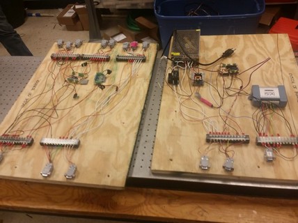
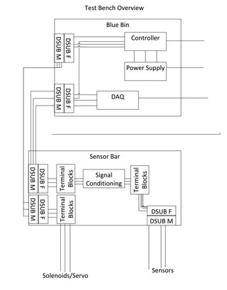
The architecture diagram in pictures below shows how parts are connected. This project is more a documented system of interconnects than an overall design project. It did include building perfboards for strain gauge amplifiers, and power electronics to supply those, as well as routing power and signals for data collection and engine control. We also had to recalibrate and re-test all of our sensors.
-
My Contributions
I designed the architecture, made the bill of materials, and oversaw and helped with the implementation of the tasks listed above.
-
Files
-
Pictures
-
Videos
This video is the first posted static fire test video that used this new setup.
Addressable LED Costume PieceAugust 2015
-
Project Overview
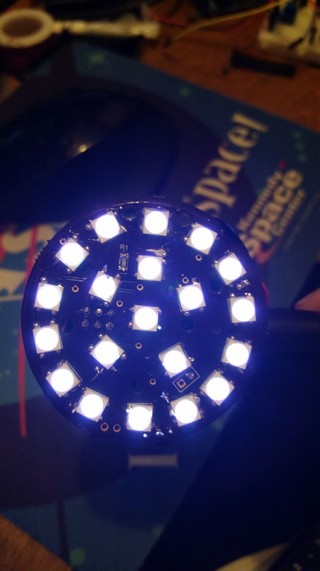
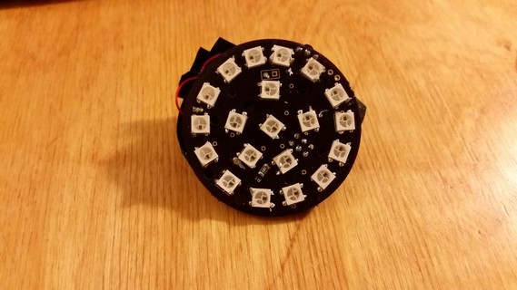
The goal of this project build an addressable LED toy that I could use as an Iron Man style Arc Reactor costume piece. It was also an experience in hardware design and printed circuit board design.
-
Project Motivation
This project was just a learning experience for me! I didn't end up using it for anything.
-
Electronics Architecture
The microcontroller used for this project was an Atmel ATtiny85. It was connected to a collection of WS2812B LEDs. It also had a built-in infrared transmitter and receiver to enable wireless control. It was all powered from a 5V barrel jack supply, which was run through a 3.3V linear regulator to power the microcontroller.
-
Software Architecture
The software for the microprocessor was based on the Arduino platform, which is mostly C with some C++.
-
My Contributions
I designed, built, and debugged the hardware and software.
-
Files
-
Pictures
-
Failures and Lessons Learned
WS2812 LEDs get really hot, which I didn't know or think about until after it was built. That makes it a rather poor costume piece.
My soldering was also very bad at this point in my career, and this was one of my first surface mount assembly attempts. It has improved a lot since.
MASA Initial Hybrid Control SystemFebruary 2015-August 2015
-
Project Overview
The goal of this project was to design and build the original electrical hardware used to test MASA's first hybrid engine. We needed to be able to remotely control several solenoids and a servo motor, as well as be able to read back a measurement of pressure in our oxidizer tank.
-
Project Motivation
This project needed to support the requirements of the propulsion team developing the hybrid engine. There wasn't as much electrical design in this project as there was choosing parts and linking them together. It also involved designing a software interface.
-
Electronics Architecture
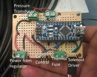
An Arduino Nano (based on an ATMega328 microprocessor) was used as the controller. It read from a pressure transducer, and controlled the servo motor used to control the main oxidizer valve. It also interfaced with a driver used to control the solenoids.
-
Software Architecture
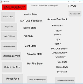
The software for the microprocessor was based on the Arduino platform, which is mostly C with some C++. A serial protocol was defined to communicate state information and commands between the microcontroller and the MATLAB interface.
-
My Contributions
I worked on the schematic, the layout, and the example software. I also helped design and run the Introduction to Arduino and Hardware Workshop.
-
Pictures
-
Failures and Lessons Learned
It was a mistake to not take time at the beginning of the testing process and define worst case requirements for both the engine team and the avionics team. Most of the issues encountered in this project were caused by last minute changes and repairs as the needs of the propulsion team evolved.
Intro to Engineering - Blimp CompetitionFebruary 2014-April 2014
-
Project Overview
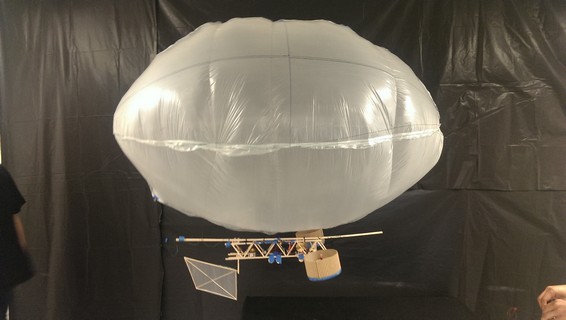
The goal of this ENGR 100: Introduction to Engineering project was to design and build a blimp that could complete a race task and a fine maneuvering task. We built the balloon out of plastic, the base out of balsa wood, and attached electronics to it.
-
Project Motivation
This project was an introduction to engineering course, so the goal overall was to teach basic engineering methods and processes. Concepts like iterative design, multidisciplinary cooperation, and planning ahead for the unexpected were taught over the course of the project.
-
My Contributions
For this project I primarily worked on the electrical and software systems..
-
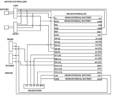
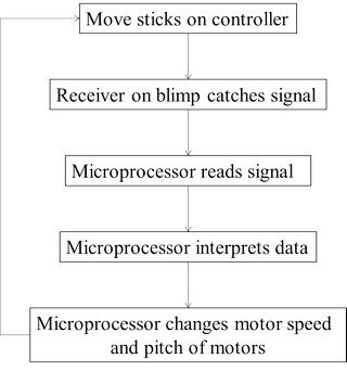
Electronics Architecture
-
Software Architecture
The software for the microprocessor was based on the Arduino platform, which is mostly C with some C++.
-
Files
Final report/presentation not posted, this project may be used again so it should not be posted online as it contains guidelines and instructions on how to complete the project. -
Pictures
Eagle Scout ProjectFebruary 2012-January 2013
-
Project Overview
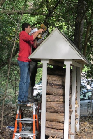
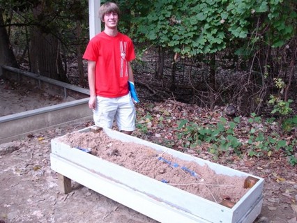
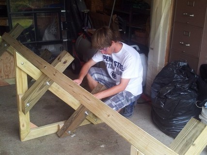
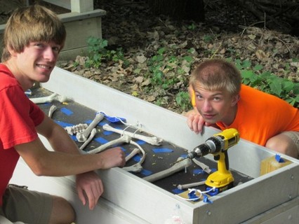
This was the project I completed as part of earning my Eagle Scout Award. I build a firewood storage structure and a dinosaur dig themed sandbox for Dinosaur Hill Nature Preserve in Rochester Hills, Michigan.
-
Project Motivation
This project needed to be substantial, and needed to be designed so that I could show significant leadership. I had grown up visiting Dinosaur Hill constantly, for classes, for camps, and just to walk through the woods. I wanted to give back to them, and they gave me the opportunity to complete this project.
As shown in the pictures in the attached report, the old firewood structure was small and on the ground, which was causing their firewood to rot. Dinosaur Hill has regular family bonfires and other events that use their firepit, so it was valuable to them to be able to have more and better treated firewood.
As a dinosaur themed nature preserve, they also had a desire for a themed sandbox that passers-by would be able to interact with. They have a much larger one they unlock for special events, but the equipment inside was too valuable to leave out without supervision.
-
Files
-
Pictures



_tn.jpg)
_tn.jpg)
